


This product is now obsolete.
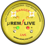
The Micro is designed to fit through the front of a control panel or switch and occupies a standard 30mm pushbutton hole. It is rated at IP 65 for Europe and NEMA 4X for USA. The front face of the Micro consists of a clear polycarbonate material, behind which are a series of LED’s and a legend displaying the following conditions :-
Phase and Neutral indication
Indication of any voltage present between 24v and 750v ac / 24v and 1000v dc – including neutral voltage if present
A safety message with instructions
The Micro contains fully encapsulated, triple redundant, electronic circuits and the connection is via a flying lead which connects to the electrical supply as close as possible to the Isolation point – i.e. immediately after the disconnect switch.
The concept of operation is that when the power supply is in the “ON” state then the LED displays on the face of the micro would be illuminated with some flashing LED’s to attract attention. These LED’s would remain operational until all voltage has decayed to less than 24v on all connections including the Neutral.
So the person performing the isolation can see that the Micro is functional with the power on and see a positive change of state after correct isolation, because Micro-Remlive will continue to give some form of illumination until all voltage connected to it is below 24 volts
Visual Safety Warning and Verification of Isolation
Reducing Risks Protecting People
REM Live Micro Installation Data Sheet
|
Supply Details
|
Connection Details Black – L1 |
|||||||||||||||||
Current, AC or DC, 5 mA (Maximum – voltage dependent)
Connect REMLIVE to the OUTGOING side of the Isolator / Circuit Breaker, making sure that the connections are Electrically and Mechanically sound and in accordance with current regulations for electrical installations. If the Isolator / Circuit Breaker is rated at more than 200 Amps, or the REMLIVE unit is mounted outside the fault free zone, connect via suitable fuses complying with current electrical regulations for electrical installations.
WARNING ! Do not fit Remlive if the unit is damaged in any way
REPLACE the REMLIVE unit if EITHER of the two sets of THREE FLASHING INDICATORS FAIL TO FLASH approximately every 1.5 SECONDS, when a live supply is connected. If uncertain about any application or aspect of fitting or operating REMLIVE, contact the supplier.
On 3 Phase installations the Neutral & Earth connections are Optional, however should two phases fail, the indicators will cease to operate if Neutral or Earth is NOT USED. Remlive Limited strongly recommend the use of both NEUTRAL & EARTH connections to ensure 100% availability of the Remlive Warning Indicator. If a Neutral connection is not available , the Neutral connection can be connected to earth, however, advise from a qualified electrical engineer should be taken before connecting in this way. Using Neutral and earth connections has the added benefit of indicting a voltage above 24volts is present – Neutral to Earth – even when all phase voltages are at zero
| In any event Remember!! |
Live Equipment Can Kill Other Safety Procedures Still Apply Test Before Touching |
To mechanically install Micro-Remlive simply drill or punch a 30mm hole with locating hole, as per a standard pushbutton.
Place Micro-Remlive in the hole, viewed from the front, and thread the locking nut along the cable. With the two small handles and locking tooth, slide along the ratchet until firmly secure. Using a screwdriver, push the locking tooth one final notch for best results. To release, rotate the handles through 90 degrees and slide locking nut off.
Standards
REMLIVE is manufactured using modern manufacturing techniques and top quality materials. It has undergone ALL the rigorous tests necessary for it to attain the CE Mark and to ensure that it conforms with the essential protection requirements of EC Directive 89/336/EEC relating to ELECTROMAGNETIC COMPATIBILTY by the application of the following standards: EN 50081 – 2 Emissions. EN 50082 – 2 Immunity.
REMLIVE also conforms with the essential protection requirements of EC Directive 73/23/EEC relating to the safety of electrical equipment by the application of the following standards: EN 61010 Low Voltage Directive.
Limitations of Use
Micro-REMLIVE is housed in a robust VO Rated special enclosure, which has been selected for its durability and protective, insulation and zero halogen properties. Micro-REMLIVE has been designed to give protection to IP65 and should ALWAYS be fitted in a accordance with the manufacturer’s recommendations.
MICRO-REMLIVE – Part No. uRL-1 LED Illumination Sequence
The following sequences are related to the illumination and connection of the Micro-Remlive – uRL-1 VISUAL SAFETY WARNING and VERIFICATION of ISOLATION DEVICE
The Four Light Emitting Diodes outer most from the centre above L1& L2, below L3 & N, will flash approximately every 1.5 seconds if Micro-Remlive detects a potential difference above
24Vac / 24Vdc between any two connected cables.