 Basket Spreader Cables
Applications
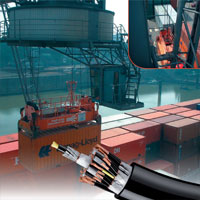
Special control cablesfor load lifting devices such as spreader with high mechanical stress in vertical free-fall basket operation in dry, humid and wet rooms and for outdoor marine environments. Used e.g. in electro-hydraulic telescopic spreader for:
- Ship to Shore (STS) cranes,
- Rail Mounted Gantry cranes (RMG),
- Rubber Tired Gantry cranes (RTG),
- Intermodal stacking cranes,
- Mobile harbour cranes …
Design
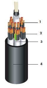
| 1. Conductor | Extra flexible, plain copper, acc. to DIN EN / IEC 60228 class 6 |
| 2. Insulation | PVC compound according to DIN EN 50363-3 |
| 3. Core assembling | Bundle stranding with/without EMC screen and heavy weight elements |
| 4. Outer sheath | Thermoplastic polyurethane according to DIN EN 50363-10-2 |
| Colour: | Black |
Marking
eg RHEYCORD(BS) YSLZ3SOE-J 44 x 2.5
300/500V I NEXANS I year
Cores Identification
DIN VDE 0293 part 308 white cores with black printed numbers + green/yellow core.
Standards
International Nexans specification UL FILE-CCN: E60419-ZIPF
Mechanical Properties
| Tensile stress of the conductor | static | 15 N/mm2 |
| dynamic | 30 N/mm2 | |
| Bending radii | according to DIN VDE 298-3, | |
| see construction characteristics | ||
| Tests | alternating/reversed bending test, torsional resistance test | |
| Travelling speed | up to 160 m/min | |
Chemical properties
Oil resistant.
For indoor and outdoor applications. Moisture, UV and ozone resistance.
Electrical and Thermal properties
| Nominal voltage | Uo/U | 450/750 V |
| Maximum operating voltage in AC systems | Um | 550 V |
| Maximum operating voltage in DC systems | Vm | 825 V |
| Test voltage | 2.0 kV in AC | |
| Current rating (A) | according to DIN VDE 0298 part 4, | |
| Max. temperature at the conductor: | ||
| – in service | + 70°C | |
| – under short-circuit conditions | + 150°C | |
| Max. surface temperature: | ||
| – fixed installation | -20 °C up to + 60°C | |
| – mobile operation | – 20 °C up to + 60°C | |
| Number of cores andnominal cross-section | Outer diameter | Weightapprox. | ||
| (mm2) | Min.(mm) | Max.(mm) | (kg/km) | |
| CONTROL | 48 x 1 | 32 | 35 | 2100 |
| 30 x 2.5 | 32 | 35 | 2200 | |
| 36 x 2.5 | 35 | 38 | 2600 | |
| 42 x 2.5 | 38 | 41 | 3100 | |
| 44 x 2.5 | 37 | 40 | 3250 | |
| 20 x 3.5 | 30 | 33 | 1850 | |
| 24 x 3.5 | 32 | 35 | 2350 | |
| 30 x 3.5 | 35 | 38 | 2800 | |
| 36 x 3.5 | 39 | 42 | 3700 | |
| 42 x 3.5 | 43 | 46 | 4700 | |
| 54 x 2.5 | 46 | 49 | 4500 | |
| 24 x 12 AWG | 33 | 35 | 2200 | |
| 36 x 12 AWG | 39.5 | 42.5 | 3500 | |
| 42 x 12 AWG | 43 | 46 | 3900 | |
| 44 xf 12 AWG | 43 | 46 | 3800 | |
| Control with Optical Fibre Element | 32 xf 3.5 + OFE | 39 | 42 | 3550 |
| Control With Concentric Screen | 48 x 1 | 38 | 41 | 2400 |
| 30 x 2.5 | 38 | 41 | 2550 | |
| 36 x 2.5 | 35 | 38 | 2950 | |
| 42 x 2.5 | 43 | 46 | 3700 | |
| 20 x 3.5 | 36 | 39 | 2100 | |
| 24 x 3.5 | 38 | 41 | 2600 | |
| 30 x 3.5 | 41 | 44 | 3150 | |
| 36 x 3.5 | 45 | 48 | 4150 | |
| 42 x 3.5 | 49 | 52 | 5250 | |
Options
- Further numbers of cores upon request
- Integrated Optical Fiber Elements
- Integrated BUS-System


