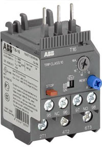
 Thermal overload relays are economic electromechanical protection devices for the main circuit. They are used mainly to protect motors against overload and phase failures. Starter combinations are setup together with contactors. Suitable for the B6/B7/VB6/VB7 mini contactors and AS block contactors (phone).
Description
- Overload protection – trip class 10
- Phase loss sensitivity
- Temperature compensation from -25 to +60 °C
- Adjustable current setting for overload protection
- Automatic or manual reset selectable
- Suitable for three- and single-phase application
- Trip-free mechanism
- Status indication
- STOP and TEST function
- Direct mounting onto mini contactors or block contactors
Application / internal function
The thermal overload relays are three pole relays with bimetal tripping elements (1 per pole). The motor current flows through the bimetal tripping elements and heats them directly and indirectly. In case of an overload (over current), the bimetal elements become bent as a result of the heating. This leads to a release of the relay and a change of the contacts switching position (95-96 / 97-98). The contact 95-96 is used to control the load contactor.
The overload relays have a setting scale in Amperes, which allows the direct adjusting of the relay without any additional calculation. In compliance with international and national standards, the setting current is the rated current of the motor and not the tripping current (no tripping at 1.05 x I, tripping at 1.2 x I; I = setting current). The relays are constructed in way that they protect themselves in the event of an overload. The overload relay has to be protected against short-circuit.
| Type | Setting range | Resistance per pole | Power loss | Short-circuit protection device |
Order Code | ||
| lower value A |
upper value A |
© | at lower value W |
at upper value W |
coordination type 2 |
||
| T16-0.13 | 0.10 | 0.13 | 106.51 | 1.1 | 2.0 | 0.5 A, Type T | 1SAZ711201R1005 |
| T16-0.17 | 0.13 | 0.17 | 62.28 | 1.1 | 2.0 | 1.0 A, Type T | 1SAZ711201R1008 |
| T16-0.23 | 0.17 | 0.23 | 37.43 | 1.1 | 2.0 | 1.0 A, Type T | 1SAZ711201R1009 |
| T16-0.31 | 0.23 | 0.31 | 20.60 | 1.1 | 2.0 | 1.0 A, Type T | 1SAZ711201R1013 |
| T16-0.41 | 0.31 | 0.41 | 11.42 | 1.1 | 2.0 | 2.0 A, Type gG | 1SAZ711201R1014 |
| T16-0.55 | 0.41 | 0.55 | 6.35 | 1.1 | 2.0 | 2.0 A, Type gG | 1SAZ711201R1017 |
| T16-0.74 | 0.55 | 0.74 | 3.62 | 1.1 | 2.0 | 4.0 A, Type gG | 1SAZ711201R1021 |
| T16-1.0 | 0.74 | 1.00 | 1.920 | 1.1 | 2.0 | 6.0 A, Type gG | 1SAZ711201R1023 |
| T16-1.3 | 1.00 | 1.30 | 1.065 | 1.1 | 2.0 | 6.0 A, Type gG | 1SAZ711201R1025 |
| T16-1.7 | 1.30 | 1.70 | 0.623 | 1.1 | 2.0 | 10.0 A, Type gG | 1SAZ711201R1028 |
| T16-2.3 | 1.70 | 2.30 | 0.340 | 1.1 | 2.0 | 10.0 A, Type gG | 1SAZ711201R1031 |
| T16-3.1 | 2.30 | 3.10 | 0.187 | 1.1 | 2.0 | 10.0 A, Type gG | 1SAZ711201R1033 |
| T16-4.2 | 3.10 | 4.20 | 0.102 | 1.1 | 2.0 | 20.0 A, Type gG | 1SAZ711201R1035 |
| T16-5.7 | 4.20 | 5.70 | 0.059 | 1.1 | 2.0 | 20.0 A, Type gG | 1SAZ711201R1038 |
| T16-7.6 | 5.70 | 7.60 | 0.031 | 1.1 | 2.0 | 35.0 A, Type gG | 1SAZ711201R1040 |
| T16-10 | 7.60 | 10.00 | 0.0193 | 1.1 | 2.0 | 35.0 A, Type gG | 1SAZ711201R1043 |
| T16-13 | 10.00 | 13.00 | 0.0131 | 1.3 | 2.2 | 40.0 A, Type gG | 1SAZ711201R1045 |
| T16-16 | 13.00 | 16.00 | 0.0078 | 1.3 | 2.2 | 40.0 A, Type gG | 1SAZ711201R1047 |
Technical Data
| Main Circuit | ||
| Rated operational voltage Ue | 690 V a.c.; – V d.c. | |
| Trip Class | 10 | |
| Rated frequency | 50/60 Hz | |
| Number of poles | 3 | |
| Isolation data | 2T1-4T2-6T3 | |
| Rated impulse withstand voltage Uimp | 6 kV | |
| Rated insulation voltage Ui | 690 V | |
| Pollution degree | 3 | |
| Electrical connection | 2T1-4T2-6T3 | |
| Connecting capacity | Solid | 1/2 x 0.75 … 1.5 mm² 1/2 x 1.5 … 4 mm² |
| Stranded | 1/2 x 1 … 4 mm² | |
| flexible with ferrule | 1/2 x 0.75 … 4 mm² | |
| flexible with ferrule insulated | 1/2 x 0.75 … 4 mm² | |
| flexible without ferrule | 1/2 x 0.75 … 4 mm² | |
| Stripping length | 12 mm | |
| Tightening torque | 1.1 … 1.5 Nm | |
| Connection screw | M4 (Pozidrive 2) | |


